配置企业使用路由策略控制L3VPN分支间用户互访示例
简介
BGP/MPLS IP VPN是一种基于MPLS的L3VPN,组网方式灵活,可扩展性好,支持大规模部署。利用BGP/MPLS IP VPN技术,可以实现位于不同地理位置的分支间安全互通或隔离。
路由策略主要实现了路由过滤和路由属性设置等功能,它通过改变路由属性来改变网络流量所经过的路径。
BGP/MPLS IP VPN结合路由策略,可以控制VPN路由的发布和接收,实现分支间特定用户的互访。
配置注意事项
- SA系列单板不支持BGP/MPLS IP VPN功能,X1E系列单板在V200R006C00版本及后续版本支持BGP/MPLS IP VPN功能。
- 此举例适用的产品和版本如表1所示。
表1 举例适用的产品和版本 系列
产品
支持版本
S5300
S5300HI
V200R002C00、V200R003C00、V200R005(C00&C01&C02)
S5310EI
V200R002C00、V200R003C00、V200R005(C00&C02)
S5320EI
V200R009C00、V200R010C00
S5320HI
V200R009C00、V200R010C00
S6300
S6300EI
V200R005(C00&C01&C02)
S6320EI
V200R008C00、V200R009C00、V200R010C00
S9300
S9303、S9306、S9312
V200R001C00、V200R002C00、V200R003C00、V200R005C00SPC300、V200R006C00、V200R007C00、V200R008(C00&C10)、V200R009C00、V200R010C00
S9300
S9310
V200R010C00
S9300X
S9310X
V200R010C00
S9300E
S9300E
V200R002C00、V200R003C00、V200R005C00SPC300、V200R006C00、V200R007C00、V200R008(C00&C10)、V200R009C00、V200R010C00
配置思路
采用如下的思路配置企业使用路由策略控制L3VPN分支间用户互访:
- PE之间配置OSPF,实现骨干网的IP连通性。
- PE之间配置MPLS基本能力和MPLS LDP,建立MPLS LSP公网隧道,传输VPN数据。
- PE上配置VPN实例,接入VPN用户,并指定不同的VPN Target,实现分支间的用户隔离。
- PE上配置路由策略,改变通过路由策略过滤的路由的VPN Target,实现分支间特定网段的用户互通。
- CE与PE之间配置EBGP,交换VPN路由信息。
- PE之间配置MP-IBGP,交换VPN路由信息。
操作步骤
- 在MPLS骨干网上配置IGP协议,实现骨干网PE间的互通
# 配置PE1。
<Quidway> system-view
[Quidway] sysname PE1
[PE1] interface loopback 1
[PE1-LoopBack1] ip address 1.1.1.9 32
[PE1-LoopBack1] quit
[PE1] vlan batch 10 100
[PE1] interface gigabitethernet 1/0/0
[PE1-GigabitEthernet1/0/0] port link-type trunk
[PE1-GigabitEthernet1/0/0] port trunk allow-pass vlan 10
[PE1-GigabitEthernet1/0/0] quit
[PE1] interface gigabitethernet 2/0/0
[PE1-GigabitEthernet2/0/0] port link-type trunk
[PE1-GigabitEthernet2/0/0] port trunk allow-pass vlan 100
[PE1-GigabitEthernet2/0/0] quit
[PE1] interface vlanif 100
[PE1-Vlanif100] ip address 172.10.1.1 24
[PE1-Vlanif100] quit
[PE1] ospf 1
[PE1-ospf-1] area 0
[PE1-ospf-1-area-0.0.0.0] network 172.10.1.0 0.0.0.255
[PE1-ospf-1-area-0.0.0.0] network 1.1.1.9 0.0.0.0
[PE1-ospf-1-area-0.0.0.0] quit
[PE1-ospf-1] quit
# 配置PE2。
<Quidway> system-view
[Quidway] sysname PE2
[PE2] interface loopback 1
[PE2-LoopBack1] ip address 2.2.2.9 32
[PE2-LoopBack1] quit
[PE2] vlan batch 10 100
[PE2] interface gigabitethernet 1/0/0
[PE2-GigabitEthernet1/0/0] port link-type trunk
[PE2-GigabitEthernet1/0/0] port trunk allow-pass vlan 10
[PE2-GigabitEthernet1/0/0] quit
[PE2] interface gigabitethernet 2/0/0
[PE2-GigabitEthernet2/0/0] port link-type trunk
[PE2-GigabitEthernet2/0/0] port trunk allow-pass vlan 100
[PE2-GigabitEthernet2/0/0] quit
[PE2] interface vlanif 100
[PE2-Vlanif100] ip address 172.10.1.2 24
[PE2-Vlanif100] quit
[PE2] ospf 1
[PE2-ospf-1] area 0
[PE2-ospf-1-area-0.0.0.0] network 172.10.1.0 0.0.0.255
[PE2-ospf-1-area-0.0.0.0] network 2.2.2.9 0.0.0.0
[PE2-ospf-1-area-0.0.0.0] quit
[PE2-ospf-1] quit
配置完成后,PE1、PE2之间应能建立OSPF邻居关系,执行display ospf peer命令可以看到邻居状态为Full。执行display ip routing-table命令可以看到PE之间学习到对方的Loopback1路由。
- 在MPLS骨干网上配置MPLS基本能力和MPLS LDP,建立LDP LSP
# 配置PE1。
[PE1] mpls lsr-id 1.1.1.9
[PE1] mpls
[PE1-mpls] quit
[PE1] mpls ldp
[PE1-mpls-ldp] quit
[PE1] interface vlanif 100
[PE1-Vlanif100] mpls
[PE1-Vlanif100] mpls ldp
[PE1-Vlanif100] quit
# 配置PE2。
[PE2] mpls lsr-id 2.2.2.9
[PE2] mpls
[PE2-mpls] quit
[PE2] mpls ldp
[PE2-mpls-ldp] quit
[PE2] interface vlanif 100
[PE2-Vlanif100] mpls
[PE2-Vlanif100] mpls ldp
[PE2-Vlanif100] quit
上述配置完成后,PE1与PE2之间应能建立LDP会话,执行display mpls ldp session命令可以看到显示结果中Status项为“Operational”。
- 在PE设备上配置VPN实例,将CE接入PE
# 配置PE1。
[PE1] ip vpn-instance vpna
[PE1-vpn-instance-vpna] route-distinguisher 100:1
[PE1-vpn-instance-vpna-af-ipv4] vpn-target 111:1 both
[PE1-vpn-instance-vpna-af-ipv4] quit
[PE1-vpn-instance-vpna] quit
[PE1] interface vlanif 10
[PE1-Vlanif10] ip binding vpn-instance vpna
[PE1-Vlanif10] ip address 192.168.1.1 24
[PE1-Vlanif10] quit
# 配置PE2。
[PE2] ip vpn-instance vpna
[PE2-vpn-instance-vpna] route-distinguisher 200:1
[PE2-vpn-instance-vpna-af-ipv4] vpn-target 222:1 both
[PE2-vpn-instance-vpna-af-ipv4] quit
[PE2-vpn-instance-vpna] quit
[PE2] interface vlanif 10
[PE2-Vlanif10] ip binding vpn-instance vpna
[PE2-Vlanif10] ip address 192.168.2.1 24
[PE2-Vlanif10] quit
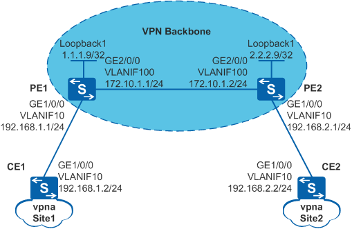
# 按图1配置各CE1和CE2的接口IP地址。
<Quidway> system-view
[Quidway] sysname CE1
[CE1] vlan batch 10
[CE1] interface gigabitethernet 1/0/0
[CE1-GigabitEthernet1/0/0] port link type trunk
[CE1-GigabitEthernet1/0/0] port trunk allow-pass vlan 10
[CE1-GigabitEthernet1/0/0] quit
[CE1] interface vlanif 10
[CE1-Vlanif10] ip address 192.168.1.2 24
[CE1-Vlanif10] quit
<Quidway> system-view
[Quidway] sysname CE2
[CE2] vlan batch 10
[CE2] interface gigabitethernet 1/0/0
[CE2-GigabitEthernet1/0/0] port link type trunk
[CE2-GigabitEthernet1/0/0] port trunk allow-pass vlan 10
[CE2-GigabitEthernet1/0/0] quit
[CE2] interface vlanif 10
[CE2-Vlanif10] ip address 192.168.2.2 24
[CE2-Vlanif10] quit
配置完成后,在PE设备上执行display ip vpn-instance verbose命令可以看到VPN实例的配置情况。各PE能ping通自己接入的CE。
 说明:
说明: 当PE上有多个绑定了同一个VPN的接口,则使用ping -vpn-instance命令ping对端PE接入的CE时,要指定源IP地址,即要指定ping -vpn-instance vpn-instance-name -a source-ip-address dest-ip-address命令中的参数-a source-ip-address,否则可能ping不通。
- 配置路由策略
# 配置PE1。
[PE1] ip ip-prefix ipPrefix1 index 10 permit 192.168.1.0 24 greater-equal 24 less-equal 32
[PE1] route-policy vpnroute permit node 1
[PE1-route-policy] if-match ip-prefix ipPrefix1
[PE1-route-policy] apply extcommunity rt 222:1
[PE1-route-policy] quit
[PE1] ip vpn-instance vpna
[PE1-vpn-instance-vpna] export route-policy vpnroute
[PE1-vpn-instance-vpna] quit
# 配置PE2。
[PE2] ip ip-prefix ipPrefix1 index 10 permit 192.168.2.0 24 greater-equal 24 less-equal 32
[PE2] route-policy vpnroute permit node 1
[PE2-route-policy] if-match ip-prefix ipPrefix1
[PE2-route-policy] apply extcommunity rt 111:1
[PE2-route-policy] quit
[PE2] ip vpn-instance vpna
[PE2-vpn-instance-vpna] export route-policy vpnroute
[PE2-vpn-instance-vpna] quit
- 在PE与CE之间建立EBGP对等体关系,引入VPN路由
# 配置CE1。CE2的配置与CE1类似,此处不作赘述。
[CE1] bgp 65410
[CE1-bgp] peer 192.168.1.1 as-number 100
[CE1-bgp] import-route direct
[CE1-bgp] quit
# 配置PE1。PE2的配置与PE1类似,此处不作赘述。
[PE1] bgp 100
[PE1-bgp] ipv4-family vpn-instance vpna
[PE1-bgp-vpna] peer 192.168.1.2 as-number 65410
[PE1-bgp-vpna] import-route direct
[PE1-bgp-vpna] quit
[PE1-bgp] quit
配置完成后,在PE设备上执行display bgp vpnv4 vpn-instance vpna peer命令,可以看到PE与CE之间的BGP对等体关系已建立,显示结果中State项为“Established”。
- 在PE之间建立MP-IBGP对等体关系
# 配置PE1。
[PE1] bgp 100
[PE1-bgp] peer 2.2.2.9 as-number 100
[PE1-bgp] peer 2.2.2.9 connect-interface loopback 1
[PE1-bgp] ipv4-family vpnv4
[PE1-bgp-af-vpnv4] peer 2.2.2.9 enable
[PE1-bgp-af-vpnv4] quit
[PE1-bgp] quit
# 配置PE2。
[PE2] bgp 100
[PE2-bgp] peer 1.1.1.9 as-number 100
[PE2-bgp] peer 1.1.1.9 connect-interface loopback 1
[PE2-bgp] ipv4-family vpnv4
[PE2-bgp-af-vpnv4] peer 1.1.1.9 enable
[PE2-bgp-af-vpnv4] quit
[PE2-bgp] quit
配置完成后,在PE设备上执行display bgp peer或display bgp vpnv4 all peer命令,可以看到PE之间的BGP对等体关系已建立,并达到Established状态。
- 检查配置结果
# 在PE上执行ping -vpn-instance命令,可以Ping通对端PE接入的Site。
以PE1的显示为例:
[PE1] ping -vpn-instance vpna 192.168.2.2
  PING 192.168.2.2: 56  data bytes, press CTRL_C to break
    Reply from 192.168.2.2: bytes=56 Sequence=1 ttl=254 time=6 ms
    Reply from 192.168.2.2: bytes=56 Sequence=2 ttl=254 time=5 ms
    Reply from 192.168.2.2: bytes=56 Sequence=3 ttl=254 time=7 ms
    Reply from 192.168.2.2: bytes=56 Sequence=4 ttl=254 time=6 ms
    Reply from 192.168.2.2: bytes=56 Sequence=5 ttl=254 time=5 ms

  --- 192.168.2.2 ping statistics ---
    5 packet(s) transmitted
    5 packet(s) received
    0.00% packet loss
    round-trip min/avg/max = 5/5/7 ms
配置文件
PE1的配置文件
#
sysname PE1
#
vlan batch 10 100
#
ip vpn-instance vpna
 ipv4-family
  route-distinguisher 100:1
  export route-policy vpnroute
  vpn-target 111:1 export-extcommunity
  vpn-target 111:1 import-extcommunity
#
mpls lsr-id 1.1.1.9
mpls
#
mpls ldp
#
interface Vlanif10
 ip binding vpn-instance vpna
 ip address 192.168.1.1 255.255.255.0
#
interface Vlanif100
 ip address 172.10.1.1 255.255.255.0
 mpls
 mpls ldp
#
interface GigabitEthernet1/0/0
 port link-type trunk
 port trunk allow-pass vlan 10
#
interface GigabitEthernet2/0/0
 port link-type trunk
 port trunk allow-pass vlan 100
#
interface LoopBack1
 ip address 1.1.1.9 255.255.255.255
#
bgp 100
 peer 2.2.2.9 as-number 100
 peer 2.2.2.9 connect-interface LoopBack1
 #
 ipv4-family unicast
  undo synchronization
  peer 2.2.2.9 enable
 #
 ipv4-family vpnv4
  policy vpn-target
  peer 2.2.2.9 enable
 #
 ipv4-family vpn-instance vpna
  import-route direct
  peer 192.168.1.2 as-number 65410
#
ospf 1
 area 0.0.0.0
  network 1.1.1.9 0.0.0.0
  network 172.10.1.0 0.0.0.255
#
route-policy vpnroute permit node 1
 if-match ip-prefix ipPrefix1
 apply extcommunity rt 222:1
#
ip ip-prefix ipPrefix1 index 10 permit 192.168.1.0 24 greater-equal 24 less-equal 32
#
return
PE2的配置文件
#
sysname PE2
#
 vlan batch 10 100
#
ip vpn-instance vpna
 ipv4-family
 route-distinguisher 200:1
 export route-policy vpnroute
 vpn-target 222:1 export-extcommunity
 vpn-target 222:1 import-extcommunity
#
mpls lsr-id 2.2.2.9
mpls
#
mpls ldp
#
interface Vlanif10
 ip binding vpn-instance vpna
 ip address 192.168.2.1 255.255.255.0
#
interface Vlanif100
 ip address 172.10.1.2 255.255.255.0
 mpls
 mpls ldp
#
interface GigabitEthernet1/0/0
 port link-type trunk
 port trunk allow-pass vlan 10
#
interface GigabitEthernet2/0/0
 port link-type trunk
 port trunk allow-pass vlan 100
#
interface LoopBack1
 ip address 2.2.2.9 255.255.255.255
#
bgp 100
 peer 1.1.1.9 as-number 100
 peer 1.1.1.9 connect-interface LoopBack1
  #
 ipv4-family unicast
  undo synchronization
  peer 1.1.1.9 enable
  #
 ipv4-family vpnv4
  policy vpn-target
  peer 1.1.1.9 enable
 #
 ipv4-family vpn-instance vpna
  import-route direct
  peer 192.168.2.2 as-number 65420
#
ospf 1
 area 0.0.0.0
  network 2.2.2.9 0.0.0.0
  network 172.10.1.0 0.0.0.255
#
route-policy vpnroute permit node 1
 if-match ip-prefix ipPrefix1
 apply extcommunity rt 111:1
#
ip ip-prefix ipPrefix1 index 10 permit 192.168.2.0 24 greater-equal 24 less-equal 32
#
return
CE1的配置文件
#
sysname CE1
#
vlan batch 10
#
interface Vlanif10
 ip address 192.168.1.2 255.255.255.0
#
interface GigabitEthernet1/0/0
 port link-type trunk
 port trunk allow-pass vlan 10
#
bgp 65410
 peer 192.168.1.1 as-number 100
 #
 ipv4-family unicast
  undo synchronization
  import-route direct
  peer 192.168.1.1 enable
#
return
CE2的配置文件
#
sysname CE2
#
vlan batch 10
#
interface Vlanif10
 ip address 192.168.2.2 255.255.255.0
#
interface GigabitEthernet1/0/0
 port link-type trunk
 port trunk allow-pass vlan 10
#
bgp 65420
 peer 192.168.2.1 as-number 100
 #
 ipv4-family unicast
  undo synchronization
  import-route direct
  peer 192.168.2.1 enable
#
return